
As simple clock built on top of an esp8266
 Helmut Pozimski
8f62464c55
main: calculate exact number of seconds before sleep time ends
Helmut Pozimski
8f62464c55
main: calculate exact number of seconds before sleep time ends
|
1 year ago | |
|---|---|---|
| Fritzing | 1 year ago | |
| LICENSES | 1 year ago | |
| main | 1 year ago | |
| .gitignore | 1 year ago | |
| CMakeLists.txt | 1 year ago | |
| Makefile | 1 year ago | |
| README.md | 1 year ago | |
| esp8266-clock_breakout.png | 1 year ago |
README.md
esp8266-clock
This repository contains a small project which uses an ESP8266 microcontroller together with a DS3231 clock and a tm1637 display module to implement a clock that occasionally synchronizes time over NTP and displays the current time coverted to a configurable local timezone. It is implemented using the ESP8266 RTOS SDK.
Prerequisites
Download the ESP8266 RTOS SDK from the github project either as a release tarball or clone the repository. Follow the instructions from the project README file to install it and ensure that you can successfully compile software that uses the SDK.
Parts list
To execute this project, you will need the following components:
- ESP8266 microcontroller board (e.g. Wemos D1 Mini v3)
- DS3231 RTC module
- TM1637 seven segment display module
- (optional) CR2032 battery to back the RTC module
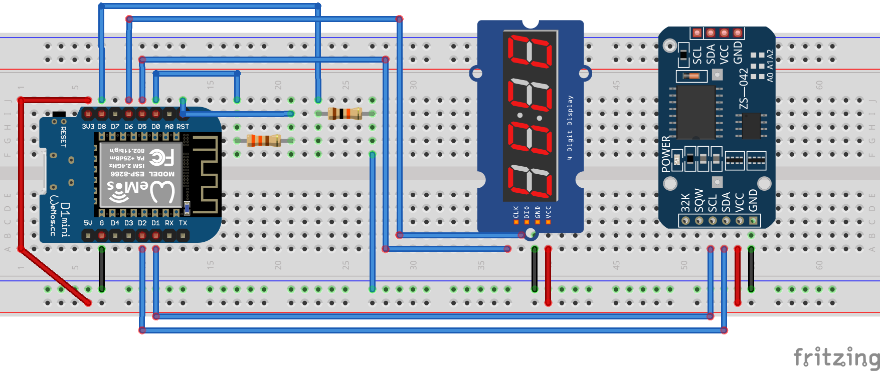
Hardware setup
Wire the SDA and SCL pins of the DS3231 module to one of the GPIO pins each as well as the CLK and DIO pins of the TM1637 module. THe example below uses the following PIN mapping:
DS3231:
- SDA -> GPIO pin 4 (D1 Mini pin D2)
- SCL -> GPIO pin 5 (D1 mini pin D1)
TM1637:
- CLK -> GPIO pin 14 (D1 mini pin D5)
- DIO -> GPIO pin 12 (D1 mini pin D6)
Also connect GPIO pin 16 (D1 mini pin pin D0) to the RST using a 330 Ohm resistor pin to ensure that the controller may enter the deep sleep state. My board would sometimes boot into flash mode after waking up from deep sleep. To prevent that I added a 10k Ohm pull-down on pin D8.
Getting started
All configuration variables that are available are listed in the file main/configuration.h. You should first fill in the blanks there and define your wifi configuration, time zone and the pins the modules are connected to.
After everything is set up, the program can be compiled with the make command and be flashed to the microcontroller by calling the flash target.
Authors
- Helmut Pozimski - Initial work - Hoshpak
License
This project is licensed under the GNU General Public License, Version 2.